Machine Parts For Reuse Newsgroup Discussion Forum > Small Size Parts
> Used
> Electrical
> Maiami
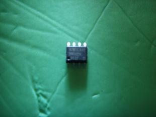
> 50 AT24C02 2-wire serial eeprom surface mount pcb chip
50 AT24C02 2-wire serial eeprom surface mount pcb chip
AT24C02 2-Wire Serial EEPROM surface mount pcb chip
Operating Temperature.................................. 55 C to +125 C *NOTICE: Stresses beyond those listed under Absolute
Applicable over recommended operating range from: TAI = 40 C to +85 C, VCC = +1.8V to +5.5V, VCC = +1.8V to +5.5V
Applicable over recommended operating range from TAI = 40 C to +85 C, VCC = +1.8V to +5.5V, VCC = +2.7V to +5.5V,
Note: 1. The write cycle time tWR is the time from a valid stop condition of a write sequence to the end of the internal clear/write cycle.
Notes: 1. For 2.7V devices used in the 4.5V to 5.5V range, please refer to performance values in the AC and DC characteristics table.
3. Available in waffle pack and wafer form; order as SL719 for wafer form. Bumped die available upon request. Please contact
Notes: 1. This drawing is for general information only; refer to JEDEC Drawing MS-001, Variation BA, for additional information.
3. D, D1 and E1 dimensions do not include mold Flash or protrusions. Mold Flash or protrusions shall not exceed 0.010 inch.
6. b2 and b3 maximum dimensions do not include Dambar protrusions. Dambar protrusions shall not exceed 0.010 (0.25 mm).
These drawings are for general information only. Refer to JEDEC Drawing MS-012, Variation AA for proper dimensions, tolerances, datums, etc.
Notes: 1. This drawing is for general information only. Refer to JEDEC Drawing MO-153, Variation AA, for proper dimensions, tolerances,
2. Dimension D does not include mold Flash, protrusions or gate burrs. Mold Flash, protrusions and gate burrs shall not exceed
3. Dimension E1 does not include inter-lead Flash or protrusions. Inter-lead Flash and protrusions shall not exceed 0.25 mm
4. Dimension b does not include Dambar protrusion. Allowable Dambar protrusion shall be 0.08 mm total in excess of the
b dimension at maximum material condition. Dambar cannot be located on the lower radius of the foot. Minimum space between
OF SALE LOCATED ON ATMEL S WEB SITE, ATMEL ASSUMES NO LIABILITY WHATSOEVER AND DISCLAIMS ANY EXPRESS, IMPLIED OR STATUTORY
WARRANTY RELATING TO ITS PRODUCTS INCLUDING, BUT NOT LIMITED TO, THE IMPLIED WARRANTY OF MERCHANTABILITY, FITNESS FOR A PARTICULAR
PURPOSE, OR NON-INFRINGEMENT. IN NO EVENT SHALL ATMEL BE LIABLE FOR ANY DIRECT, INDIRECT, CONSEQUENTIAL, PUNITIVE, SPECIAL OR INCIDENTAL
DAMAGES (INCLUDING, WITHOUT LIMITATION, DAMAGES FOR LOSS OF PROFITS, BUSINESS INTERRUPTION, OR LOSS OF INFORMATION) ARISING OUT
OF THE USE OR INABILITY TO USE THIS DOCUMENT, EVEN IF ATMEL HAS BEEN ADVISED OF THE POSSIBILITY OF SUCH DAMAGES. Atmel makes no
representations or warranties with respect to the accuracy or completeness of the contents of this document and reserves the right to make changes to specifications
and product descriptions at any time without notice. Atmel does not make any commitment to update the information contained herein. Unless specifically provided
otherwise, Atmel products are not suitable for, and shall not be used in, automotive applications. Atmel s products are not intended, authorized, or warranted for use
c Atmel Corporation 2005. All rights reserved. AtmelR, logo and combinations thereof, Everywhere You AreR and others, are registered trademarks