Machine Parts For Reuse Newsgroup Discussion Forum > Small Size Parts
> Non functional
> Mechanical
> St. Louis
> Hp agilent 70843B bert error performance analyzer
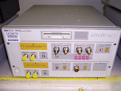
Hp agilent 70843B bert error performance analyzer
Hewlett Packard 70843B BERT Error Performance Analyzer, 0.1-12 Gbit/s, Opt. UHF GB00000537.
Use Gbit testers to measure bit error ratio (BER) and to verify the performance and quality of your components and system hardware.
Lightwave submarine cable systems
SONET/SDH synchronous network transmitters and receivers
Optical amplifiers and modulators
Multiplexers and output drivers
For high-performance pattern generation and error analysis across the entire 100 Mb/s to 12 Gb/s range, use an HP 71612B error performance analyzer with optional low-rate clock.
Both pattern generator and error analyzer provide a wide range of PRBS and user-defined patterns, with versatile triggering facilities. And to help you identify the address of the errored bits use optional error location analysis. Once the position of an errored bit is identified, the flexible triggering features can be used to view the errored pattern on an oscilloscope for further diagnosis.
Makes it easier for you to find the source of systematic errors Vital when you re under continuous pressure to develop more reliable high-speed components and subsystems.
Locate the cause of systematic errors causing a specific bit to change value. Just specify any bit in a user-defined pattern and perform bit error measurements upon it.
Essential when trying to locate the cause of systematic errors which affect longer runs of bits, for example a corrupt header in a SONET or SDH frame. Perform bit error rate measurements on a range of bits within a user-defined pattern.
Helps you discriminate between random and systematic errors.In a user-defined pattern,automatically highlight the position of each errored bit in turn displaying the address of the errored bit and show the surrounding bit pattern. Then automatically measure BER of each errored bit. If the error rate of a captured bit remains significant over a period,there is probably a pattern dependent, systematic error.
PRBS: 2 to the 31 -1, 2 to the 23 -1, 2 to the 15 -1, 2 to the 10 -1, 2 to the 7 -1.
User-defined pattern: Up to 8 Mbit.
Zero substitution: Extends the longest run of zeros up to pattern length less one bit on patterns 2 to the 13, 2 to the 11, 2 to the 10, 2 to the 7.
Variable mark density ratio: 1/8 to 7/8 in 1/8 steps on patterns 2 to the 13, 2 to the 11, 2 to the 10, 2 to the 7.
STM-64 and OC-192 patterns: Samples supplied on disk along with other stress patterns.
In the pattern generator,any pattern may be split into two equal-length patterns, with hitless switching between them.The user-defined patterns may be loaded from, or saved to, a 3- inch,MS-DOS format floppy disk.
There are inputs for an external clock, external error inject, alternate-pattern switch and data output on/off switch. There are outputs for clock and inverted clock, data and inverted data and pattern trigger, sub-rate (quarter-rate)clock; also four outputs for quarter-rate data.
Frequency range: 100 MHz to 12 GHz
Interface: 0.45 to 0.90 V p-p, dc coupled, 50 ohms. (=10 GHz), 0.65 to 0.9 V p-p (>10 GHz)
Interface: Complementary, dc coupled, 50 ohms, reverse terminated. (Independent control of outputs available)
Amplitude:0.5 to 2 V p-p in 10 mV steps
Range: +1.5 to -3.0 V in 10 mV steps
Interface: Complementary, dc coupled, 50 ohms, reverse terminated NRZ, normal or inverted. (Independent control of outputs available)
Amplitude: 0.5 to 2 V p-p in 10 mV steps
Transition times (10%to 90%): (10% to 90%): < 30 ps (typical at 2 V p-p)
Jitter: < 20 ps p-p; < 15 ps p-p at 10 Gb/s
Clock/data delay: 1 ns (100 MHz to 500 MHz),one clock period (500 MHz to 12 GHz)
Clock and data outputs subrate
Frequency range: 1/4 of main clock rate
Interface: dc coupled, 50 ohms, reverse terminated
Amplitude: 0.5 to 1 V p-p in 10 mV steps
Range: 0 to -2.0 V in 10 mV steps
Trigger output: Pattern; clock/32; clock/8
Internal: Single on command, or fixed ratio 1 in 10 n bits, where n =3 to 9
External: TTL levels (active low)
The error detector has clock and data inputs and an input which inhibits error counting. There are outputs for errors and pattern trigger. The error detector has both manual and automatic setting of decision threshold and clock/data phase alignment.
Interface: 0.45 to 0.90 V p-p dc coupled, 50 ohms to 0 V or -2 V
Sensitivity: < 200 mV p-p (typical at 10 Gb/s)
Sensitivity: < 50 mV p-p (typical for 2 to the 23 -1 PRBS input at 10 Gb/s. 0 V high level)
Impedance: 50 ohms to 0 V or -2 V, dc coupled
Decision threshold range: +1 to -3 V in 1 mV steps
Clock/data phase alignment: 1 ns (100 MHz to 500 MHz); 1 clock period (500 MHz to 12 GHz)
Trigger output: Pattern or clock/8
Error output: 0 to -0.4 V nominal
Measurement modes:Manual, single period, repetitive period
Measurement period: 1 s to 100 days 10, 100, 1000 errors; 10 to the 7 to 10 to the 15 bits
Pattern synchronization: Automatic or manual
Selectable threshold: 1 to the -1 to 10 to the -8
Audible output: Proportional to error ratio
Result logging: Time-stamped results to an external printer
Option UHF = Clock Source Not Included
UHF: 0.1 to 12 Gb/s error performance analyzer with pattern generator and error detector (no clock source provided)