Machine Parts For Reuse Newsgroup Discussion Forum > Large Size Parts
> Used
> Mechanical
> New avr microcontroller development board SKU190
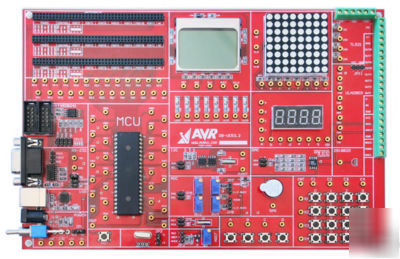
New avr microcontroller development board SKU190
On-board resources Description:
The development board has the following resources:
Power parts: the 12V input voltage, the development board to provide high stability of the 3.3V, 5V and 12V power supply, with power indicator, polarity protection circuit and switch. Also onboard are several high-frequency and low frequency power supply filter capacitor.
ISP download interface: the standard 10PIN ISP, download interface for AVR program downloads.
JTAG emulation interface: JTAG emulation debug interface, using JTAGICE online debugging.
Chip socket: PORTA, PORTB, PORTC, PORTD, respectively led to 32 sockets, JTAG & ISP, reset, crystal oscillator, power supply pins are directly linked with the chip connection. Some can only use a fixed-pin jumper to connect via an external function, such as serial, I2C, AT45DB041.
Crystal reset circuit: development board to provide a 7.3728M crystal and a crystal slot, may be their own choice of the experimenter.
Expansion Slots: 3 slots reserved for the board, according to Power, Control, Port, NC's pre-defined format, in which Power provides 3.3V, 5V, and 12V two kinds. Board expansion slot is compatible with the extensions can be achieved other special functions has been expanded, is fully compatible with ATmega128 functional board.
Serial Port: Use the MAX232 chip for serial communication control, standard RS232 interface.
USB: with USB-serial realization CP2102 function.
4 * 4 matrix keyboard: 16 keys are allowed to carry into a 4 4 matrix keyboard, Int interrupt interface, the full realization of the keyboard interrupt scanning requirements.
18B20: temperature sensor chip.
24C01: external expansion EEPROM, with the microcontroller through the I2C communication mode.
ADC: analog-digital conversion circuitry, which then is used with multiple adjustable resistor divider and testing.
DAC: digital-analog conversion circuit, DDS functions. Can be used to generate sine wave, sawtooth, square wave, and other waveforms, analog signals, etc.
Buzzer: Using a PNP transistor to control the passive buzzer for sound, program alarm or play music.
5110: Nokia 5110 LCD screen can be used to display text, pictures and animation.
4 seven-segment digital tube: four in one integrated digital tube display, using dynamic scanning to achieve display.
High drive capability of the I / O external interfaces: ULN2803 to provide 8-channel I / O interfaces. P521 offers 4-channel optocoupler circuit.
AT45DB041: External 4M flash memory chips, with the microcontroller through the SPI communication.
Each experiment provide independent schematic and detailed program documentation and comments.
Key input detection experiments
Fuse, the clock running on the impact of
Principle of the experimental Timer
1S timer TIMER1 Timing Experiment
1S timer TIMER2 Timing Experiment
Timer timer0 CTC mode generated square-wave test
Global variable to achieve long-timing experiments
Practical exact software delay functions
Principle of the experimental interruption of
EEPROM operation of the experimental
Start recording the experiment with the number of CPU
Compilation of experimental variables to initialize EEPROM
Write a flash through the Bootloader
Bootloader update via serial port
Demonstrate the use of discrete independent keys
Matrix keyboard usage examples
Matrix keyboard interrupt example
Buzzer operation of experimental
A digital control from 0 to 9 second refresh timer
The modular digital control program
Serial procedures easy to understand
Serial port interrupt mode operation
Common IO port to achieve USART
Pairs of computer communication through the SPI port
AD conversion results through the LED display
Two-way AD converter LCD display
LED brightness control via keypad
DA specify the voltage output test
TWI write a simple experiment 24C01
Dot-matrix display the letters
DS18B20 read the temperature reached the serial port
5110 LCD display English characters
ULN2803 to drive a stepper motor test
P521 Detection of an external high-voltage switches
Digital Multi-function Electronic Clock
Development Board Frequently Asked Questions
1, ask: Why not use self-locking socket?
A: The development board and the general development board is different since he does not need frequent pulling chips, but through the ISP and JTAG interfaces burning program and debug.
We use the military industrial grade socket hole socket, the quality is very good, close contact, plug the number of tens of thousands of times, and made self-locking socket contacts often occur bad situation.
2, ask: Why not add a lot of board and seven-segment LED digital tube.
Some of the development board has 74 series of chips, but the 74 series of chips casual ride with a 10000 with a circuit board can be verified, if they are to achieve the development board, and we think it is a waste of resources, student-level only a small board to do such a thing.
Our development board not do such a simple device stacking, we have a truly exceptional development of useful chips, AT45DB041, 24C01 and so on.
3 Q: Why on-board look sparse?
A: The development board used in all SMD components, and does not require use of the devices are in the back of the development board, and only show that button, jumper, socket and so it put a positive. Development board for the location of each device have carried out optimization of treatment, and to give full consideration to ergonomics, the various components of the connection seat location and the space occupied by the experiments are repeated several times revised finalized, and has done so space utilization and to facilitate optimization of stacked plug.
4, Q: Why did not commonly used on-board LCD interface?
A: Actually, a little bit microcontroller-based people, we know that LCD's use a little snack, then solder a cable can come out with a pin direct plug in LCD is not safe and practical manner. The development board provides three expansion slots, and the whole open IO port socket, you can easily put liquid crystal with our development board to link.
5, Q: Why not do switch 51 and AVR development board?
A: Yes, 51 can then be used for AVR development board, all students level, No one in the product development side with 51, while with the AVR, since you have chosen AVR, you should know that the high performance AVR, far beyond 51.
6, upper left corner of the development board slot is what for?
A: This is our development board expansion slot, according to our rules of the definition of a group of connections, we will develop a series of development boards expansion boards, such as: OSD video overlay board, display board (including a variety of commonly used liquid crystal) , storage board, network board (TCP / IP, SCM), for movement control panel, MP3 panels.
7, why use the stacked plugs to connect?
A: The unique stacked plug design, SCM resources can be fully open and can be a point with a number of lines, this is the first DuPont could not be achieved in the development of some procedures need to share it is very meaningful when the IO port.
The development board used in stack are gold-plated plugs and seat, reliable, and can accept hundreds of thousands of times the plug, which can ensure the development board's use of time, one input, lifetime use, of course, these plugs to the development board increase in a lot of cost.
The development board packing list
Debugging a good development board 1
1 parallel port download cable ISP
Program examples and information on CD-ROM 1