Machine Parts For Reuse Newsgroup Discussion Forum > Large Size Parts
> Non functional
> Electrical
> Maiami
> Gaumer circulation heater QMSD1035 control panel 11225
Gaumer circulation heater QMSD1035 control panel 11225
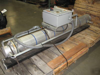
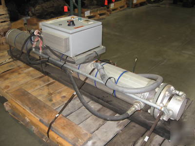
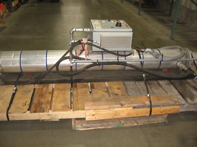
Gaumer Process Circulation Heater (Used)
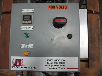
Comes With Electrical Control Panel
Price new would be almost $ 15,000
Gaumer SN Shows Build Date of 2005
We used this to preheat transmission fluid (ATF) for running in Allison Automatic Transmissions during dyno testing. It saves a great deal of time vs. using the transmission heat generation method. For more information on the unit to check for your usage you will need to contact Gaumer in Houston, TX. (***) 329-0231.
Unit was in perfect working order when we took it out of service. We eliminated one of our test facilities.
* It can also be picked up locally if preferred
Below is the circulation heater manual. I also can email PDF attachments of all wiring and specs for the control panel by serial number provided to me by Gaumer Process.
CIRCULATION HEATER INSTALLATION AND OPERATION MANUAL
a. All work should be performed by qualified personnel
b. Heater assembly must be used only in the service that the heater was designed to heat.
a. Provide adequate space for mounting of the heater. Proper spacing must be provided for removal of heating elements.
b. Heater must be mounted securely on one end with guided mounts on the opposite end to allow for expansion during heat-up. Please note correct mounting arrangement on attached general arrangement drawing. Heater must be mounted in its design orientation per the drawing. If the design orientation is to be changed (vertical design to horizontal mounting, horizontal design to vertical mounting, or reversing the inlet/outlet nozzles), please contact Gaumer Process Heaters to determine suitability. Attach piping connections as shown on the general arrangement drawing.
a. Please refer to the enclosed wiring diagram for proper installation of wiring for the heater.
b. Each heater must be protected by a suitably rated over current device.
c. Conduit connections have been provided in heater housing for power wiring and temperature sensor wiring. It is NOT recommended to run temperature sensor wiring in the same conduit or cable as the power wiring.
d. Wire sizing for power wiring and temperature sensing wiring is the responsibility of the end user recognizing the current load of the heater, the distance from the power source, and the system over-current protection. The requirements of the National Electrical Code (NEC)/(Canadian Electric Code (CEC) in Canada) must be followed. Wire must be rated per NEC (CEC) considering system ambient temperature in the housing and the current carrying capacity.
e. If temperatures in the heater housing are anticipated to rise above standard wire rating, high temperature wiring may be required for installation to the heater. Please contact Gaumer Process Heaters for assistance with high temperature wire requirements.
i. Gaumer provides flying leads rated at 1000 f (537 C) as a standard. If connecting to these leads outside of the terminal housing, an external junction box certified for the area classification with a seal (EYS) must be used. Refer to local code requirements for maximum distance of the seal from the heater housing. The overall hazardous location designation of the heater is governed by the device with the lowest hazardous location rating (E.G. Terminal box/cover ratings).
4. Over-Temperature Protection
A high temperature limit device is required to protect the heater and provide a safety limit when heating hazardous liquids or gases. DO NOT make any modifications to high limit devices provided without consulting with factory. If a high temperature limit device is not provided, the end user is responsible for providing high temperature limit control. Gaumer Process Heaters assumes no responsibility for operating the heater without a high temperature limit control.
If an over temperature controller (OTC) or high temperature switch (TSH/TSHH) has been provided in the control panel, it must be set to the appropriate temperature setting before the system is put into service. WARNING WHEN HEATING FLAMMABLE OR COMBUSTIBLE GASES OR LIQUIDS, DO NOT SET THE OTC HIGHER THAN 80% OF THE AUTO-IGNITION POINT OF THE GAS OR LIQUID! Typical analog OTC s will be mounted on the back pan of the control panel and will have an adjustable dial. This dial should be set to the proper temperature before energizing the system. If a digital indicating OTC has been provided, it must be energized before a temperature setting can be set. .
b. Check the resistance from each heater leg to ground. Do not energize the system if readings are below one Mega-ohm. See immersion heater installation sheet for more details.
c. Check the resistance between circuit legs. Refer to heater wiring diagram for proper resistance for each leg.
e. Ensure that the control thermostat, thermocouple, RTD, etc. are properly connected and set prior to energizing the heater. If a manual cutout device is installed in the heater housing, ensure the power is disconnected and locked out before opening the heater housing.
f. DO NOT operate the heater in hazardous areas without a suitable terminal enclosure. Refer to the general layout drawing for heater terminal housing classification.
g. DO NOT install heater in any system where the operating temperature and/or pressure may exceed the rating of the flange or body of the heater.
b. When performing any maintenance on the heater, all safety regulation must be followed. Approved safety lockout procedures must be followed before opening the heater or heater electrical housing.
1. Inspect equipment for leaks or visible damage
1. Open terminal housing and ensure it is dry and clean.
2. Check the resistance between each circuit leg and ground. See Section 4.b.
3. Check all terminals for damage and to ensure that all terminals are tight and secure. Care should be taken not to over-tighten terminals.
4. Check resistance between circuit legs. See Section 4.c.
6. Check enclosure gasket if provided and replace if damaged.
1. Open terminal housing and mark and disconnect all incoming wiring. Disconnect conduit. Check the housing to ensure it is clean and dry.
2. Note the position of the over-temp thermocouple, which is marked on the heater flange. Remove bolts from heater and pull heater bundle. Care must be taken in removing the bundle not to damage the elements.
3. Check heater elements for any sign of buildup of foreign materials. If buildup is noted, clean elements. Check over-temp thermocouple to ensure it is properly secured to the element. If the thermocouple is removed for any reason, it must be re-attached to the same element in the same location.
4. Perform items 2 through 5 of Semi-Annual maintenance shown above.
5. Reinstall heater bundle using a new gasket and taking care not to damage the elements. Note the position of the over-temp thermocouple. Heater MUST be reinstalled in the same orientation as when it was removed.
6. When bolting the heater into place, proper tightening procedures and torque must be used to ensure proper seating of the gasket.
7. Reconnect conduit and wires using care to reconnect to the proper terminals.
8. Close housing cover using new gasket if necessary.
9. When restarting the heater, monitor for leaks.